
Quicklinks for this tutorial
- Installing and configuring ARDUINO
- Installing the ESP32 Board manager
- Connecting ESP32-PICO to your computer
- Setting up your 46elks configuration
- Editing and uploading your code
- Success
Installing and configuring ARDUINO
If you haven’t already, download and install Arduino from www.arduino.cc/en/software
During the installation process you can keep all the default settings.
Arduino IDE (integrated development environment) is a software application that provides
us the means and tools to develop and transfer the code needed for our microcontroller to work.
Installing the ESP32 Board manager
For the example code to run on our microcontroller, we need to install a board manager that will enable Arduino IDE to communicate with our microcontroller. In this case we are using an ESP32 microcontroller and for this purpose we need to install the “ESP32 Board manager”.
- Open up the installed arduino IDE
- From the top menu choose ‘File’ → ‘Preferences’
- Once you have opened the preferences menu paste the following URL following into the section called ‘Additional Boards Manager URLs’: https://dl.espressif.com/dl/package_esp32_index.json
- Click ‘ok’
- From the top menu choose ‘Tools’ → ’Board:’ESP32 Pico Kit’ → ‘Boards Manager’
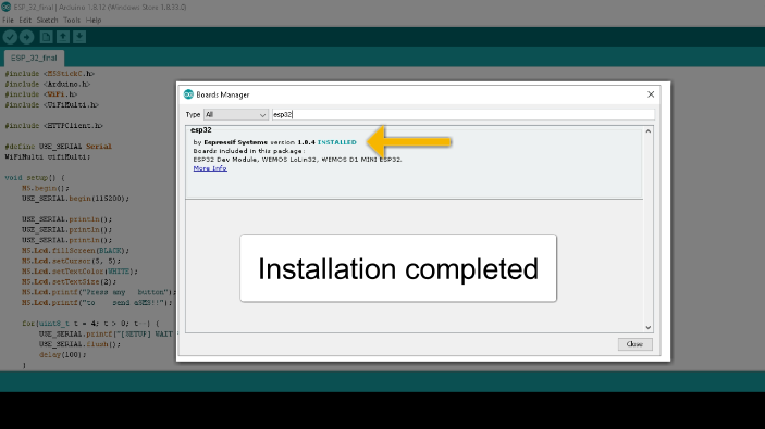
- Once you have opened ‘Boards Manager’ type ‘ESP32’ in the search bar and a package should appear. Install this package by selecting ‘install’.
If this has been done successfully you should see this.
Connecting ESP32-PICO to your computer
Now we are going to connect ESP32-PICO to our computer
- Connect your ESP32-PICO microcontroller using your USB cable to your USB port.
- Verify that drivers are installed successfully by checking the active ports on your operating system before you plug in the microcontroller and after.
- From the top menu select ‘Tools’ → ‘Upload Speed’ → ‘115200’
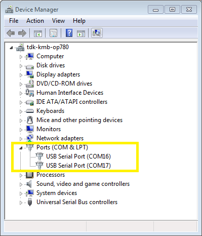
- Select the port that the microcontroller has connected to. To find out exactly what port the microcontroller is connected to, you should follow the instructions in step 2.
Windows OS has a device manager which will allow you to see under Ports (COM & LPT)what exact port the device you just plugged in it occupies.
The same can be done for Mac OS by running the command in the terminal
ls /dev/cu.*Ls /dev/tty*An important note here! Upload speed is selected to 921600 by default. Try lowering it to Upload Speed : 115200 as many users complained about getting espcomm_sync failed error when trying to upload the sketch at 921600 speed.
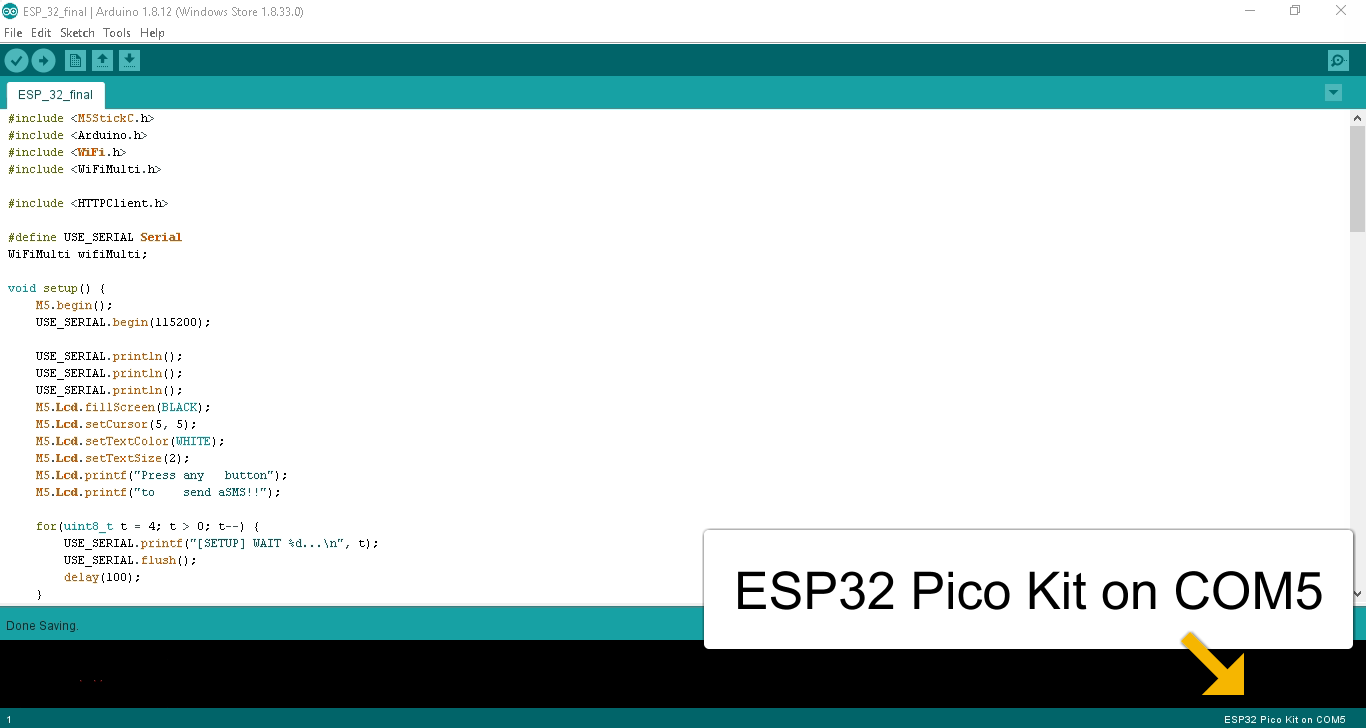
If all goes well, you should see something like this.
If the device is not connected you should get a warning saying:
Failed to execute script esptool
The selected serial port Failed to execute script esptool
Does not exist or your board is not connected.
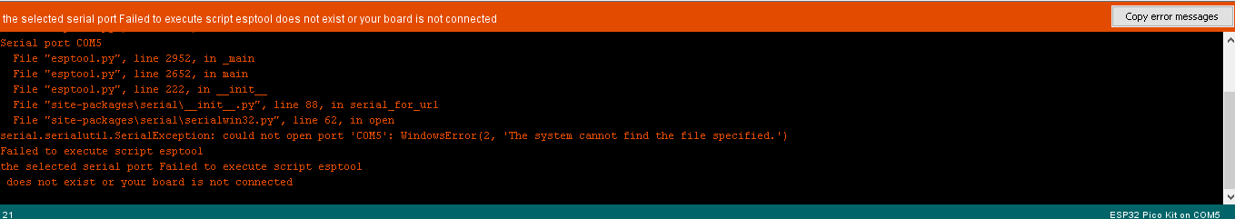
The way you go about fixing this is checking the computer's USB connection with the microcontroller, or you have chosen the wrong port. This usually happens when you have more devices connected to your computer's USB ports.
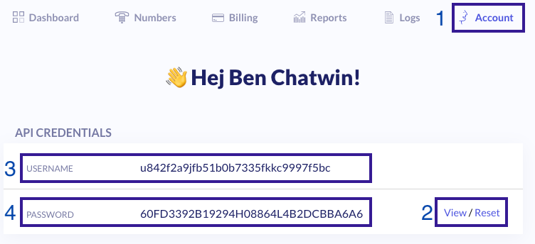
Setting up your 46elks configuration
Next, we need to authorise our request. To do this we can visit our account
dashboard and copy and paste the username and password. Here is a link to
your dashboard. Find out more about authentification here.
If you do not have an account you will need to create one.
Editing and uploading your code
Now all that is left is to add our code and run it. The code is below the instructions
- In the top menu select ‘File’ -> ‘New’
- Once a new sketch has opened, copy and paste all the code below.
- Make the following changes to the code:
- From the top menu select ‘tools’ → ‘serial monitor’. If you are getting unreadable characters in the serial monitor windows you may need to adjust your ‘Upload speed’ (Mentioned in “Connecting ESP32-PICO to your computer” chapter - step 3.)
- If you have made all the changes to the code in the Arduino menu (just below the top menu) select the arrow icon to save and start compiling your project.
Update your wifi details
wifiMulti.addAP("wifi network name", "wifi network password");Change the ‘sender’ and the ‘recipient’ of the SMS message.
The “from” number should be your own phone number, a 46elks phone number or a text-sender-id. More information on this here.
The “to” number should be the number you want to send messages to. For testing it is best to use your personal number.
int httpCode = http.POST("from=”ESP32”&to=+46123123123&message=Hej");#include < M5StickC.h >
#include < Arduino.h >
#include < WiFi.h >
#include < WiFiMulti.h >
#include < HTTPClient.h >
#define USE_SERIAL Serial
WiFiMulti wifiMulti;
void setup() {
USE_SERIAL.begin(115200);
USE_SERIAL.println();
USE_SERIAL.println();
USE_SERIAL.println();
for(uint8_t t = 4; t > 0; t--) {
USE_SERIAL.printf("[SETUP] WAIT %d...\n", t);
USE_SERIAL.flush();
delay(1000);
}
wifiMulti.addAP("sonoff", "sonoff*11");
// add your Wifi
}
void loop() {
// waiting for WiFi connection
if((wifiMulti.run() == WL_CONNECTED)) {
HTTPClient http;
USE_SERIAL.print("[HTTP] begin...\n");
// configure server and url
http.begin("https://api.46elks.com/a1/sms");
http.addHeader("Content-Type", "application/x-www-form-urlencoded");
http.setAuthorization("ae7d33d5b324edc91cb8e61f35c18e02d", "3A925F02297D0B10835ADE2B59FC580C");
int httpCode = http.POST("from=ESP32&to=+385996768133&message=This is working!");
USE_SERIAL.print("[HTTP] GET...\n");
// start connection and send HTTP header
httpCode = http.GET();
// httpCode will be negative on error
if(httpCode > 0) {
// HTTP header has been send and Server response header has been handled
USE_SERIAL.printf("[HTTP] GET... code: %d\n", httpCode);
// file found at server
if(httpCode == HTTP_CODE_OK) {
String payload = http.getString();
USE_SERIAL.println(payload);
}
} else {
USE_SERIAL.printf("[HTTP] GET... failed, error: %s\n", http.errorToString(httpCode).c_str());
}
http.end();
}
while(1){};
// while loop was put here in order for the code to be run once
// and the reason why you get one SMS
}Success
Congratulations and welcome to the world that is the Internet of Things. This code can easily be modified to utilise other SMS API features. This is a very basic introduction, from here you can add other API features to your microcontroller such as making phone calls. We would love to share your code examples with our community. All samples can go to help@46elks.com.


